RAID configuration, including the number of disks used, determines the type. As a reminder, the RAID that stands for Redundant Array of Independent Disks or Redundant Independent Disk Array is a storage solution that distributes data across multiple small disks that together form a single system. In addition to being less expensive, this device has a high level of performance and data security as RAID tolerates breakdowns better.
Today, there are nearly twenty types of RAID, if not more including configurations sometimes considered obsolete- among which is the RAID 2. Of all these RAID configurations, the most common are the RAID 0, RAID 1, RAID 10, RAID 2, RAID 3 and 4, RAID 5 or RAID 6.
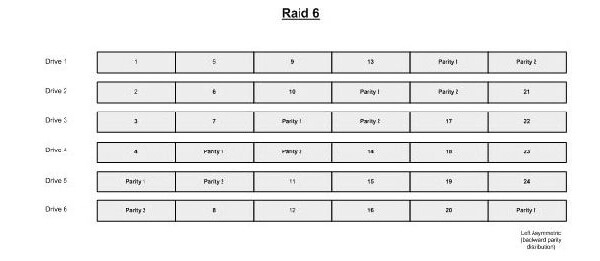
RAID 0 is a system that uses only two disks and provides fast access to data. The RAID 1 also uses two disks and writes duplicate information. If one of the disks is damaged, you will find your data on the other. To benefit from the performance of RAID 0 and the security offered by RAID 1, RAID 5 was created. With a good distribution of data, RAID 5 combines speed and fault tolerance. The RAID 6 has the same advantages as RAID 5, but with the added bonus of better writing speed.
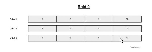 RAID 0
RAID 0 is the classic data stripping configuration, where data is written across all drives resulting in faster access. However, this performance carries a risk, if one or more disks cause a disaster in a RAID 0, then a serious loss of data can occur. The diagram below shows how the data is distributed across the matrix.
An example of a data recovery situation: a file was created that occupied data stripes 1 – 4, if drive 2 were to fail and the 2nd stripe lost, the file would most likely become corrupted. Another way to look at it would be if one drive fails, the largest possible good file would have to be smaller than the combined size of the remaining stripes.
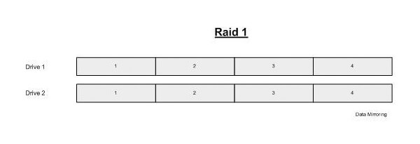 RAID 1
This is the RAID level that sets up disk mirroring; the data on the primary disk is duplicated onto the other. There are no performance gains for this RAID, but if one drive fails, then you will have a backup on the second one.
 RAID 0+1 and 1+0
To gain performance and/or additional redundancy the standard RAID levels can be combined to create hybrid or nested RAID levels, RAID types that provide redundancy are typically combined with RAID 0 to boost performance.
As you can see from the diagrams below, these two levels of RAID are a combination of RAID 0 and RAID 1. The difference between the two is the actual position of the RAID array, shown by the diagrams where the bands are in bold.
RAID 01 is configured so that RAID 0 is a mirror copy.
The advantage is that when a drive fails in one of the level 0 arrays, the missing data can be transferred from the other array. However, adding an extra hard drive to one stripe requires you to add an additional hard drive to the other stripes to balance out storage among the arrays.
A disadvantage for this configuration is that is cannot recover from two simultaneous drive failures, unless the drives are from the same data stripe. In the diagram; if drives 1 and 5 failed the RAID could be rebuilt, but if 1 and 4 failed it would result in data loss.
RAID 10
RAID 10 is configured so that the RAID 0 is split across two RAID 1 arrays.
A big advantage to RAID 10 is all but one drive from each RAID 1 array could fail without any data loss. However, if the failed drive is not replaced, the single working drive in that array becomes a single point of failure for the entire system, if that last drive goes all data within the array is lost.
The RAID nesting technique can be used for other RAID levels as well, most commonly on RAID 5 but it can also be applied to other levels like 3 and 6, producing levels such as 50, 51, 60, 61, 30 and 03.
RAID 2
RAID 2 comprises of data striping at a bit level with a dedicated parity drive. This level uses hamming error detection codes and is intended for use on drives that do not have built-in error detection. For this reason, RAID 2 is not commonly used anymore.
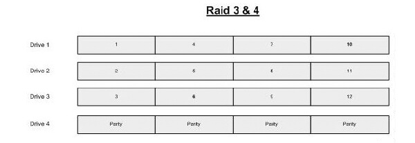 RAID 3 and 4
RAID 3 and 4 both use striping with a dedicated parity drive, the difference between the two is that RAID 3 stripes at the byte level while RAID 4 stripes at the block level. RAID 3 is seldom used these days due to the poor performance of byte level striping, RAID 4 is better with block level striping but still suffers slower write performance due to the parity having to be updated on every write.


 United States | English
 Locations
 Search


 Back to listing
 RAID 0
 RAID 1
 RAID 0+1 and 1+0
 RAID 3 and 4
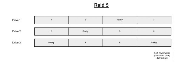 RAID 5
 RAID 6


